How to Build a 5-Channel Smart Switch Compatible With Alexa
Cloud-based smart switches are easy to set up, but they come with risks. So take matters into your own hands.
To make a home smart, you need smart switches and sensors to control Wi-Fi, RF or Zigbee connections. There are several brands that offer smart switches that you can simply unbox and deploy using their cloud services.
But if you want to build a completely private smart home, you don’t want to rely on third parties. You never know when they might shut down their cloud services. Therefore, safety and reliability are major concerns. Luckily, it’s much easier to build smart switches that work with Alexa and smart home automation software like Home Assistant.
What you need to build a smart switch
Let’s say you want to build a 5 channel smart switch that will allow you to control up to 5 different devices up to ~2 amps at 220V or 110V. To build this smart switch you will need the following:
- A D1 Mini
- A Hi-Link 5V 5W or 10W power supply
- Two 6-pin screw terminals
- A 2-pin screw terminal
- Five 220Ω ¼ watt resistors
- Five 1KΩ ¼ watt resistors
- Five optocoupler ICs MOC3021
- Five triacs, like BTA12, BTA16 or similar. We used the BTA16.
- A prefabricated or general circuit board for mounting and soldering all components
- soldering iron and tin
- wires to connect your load
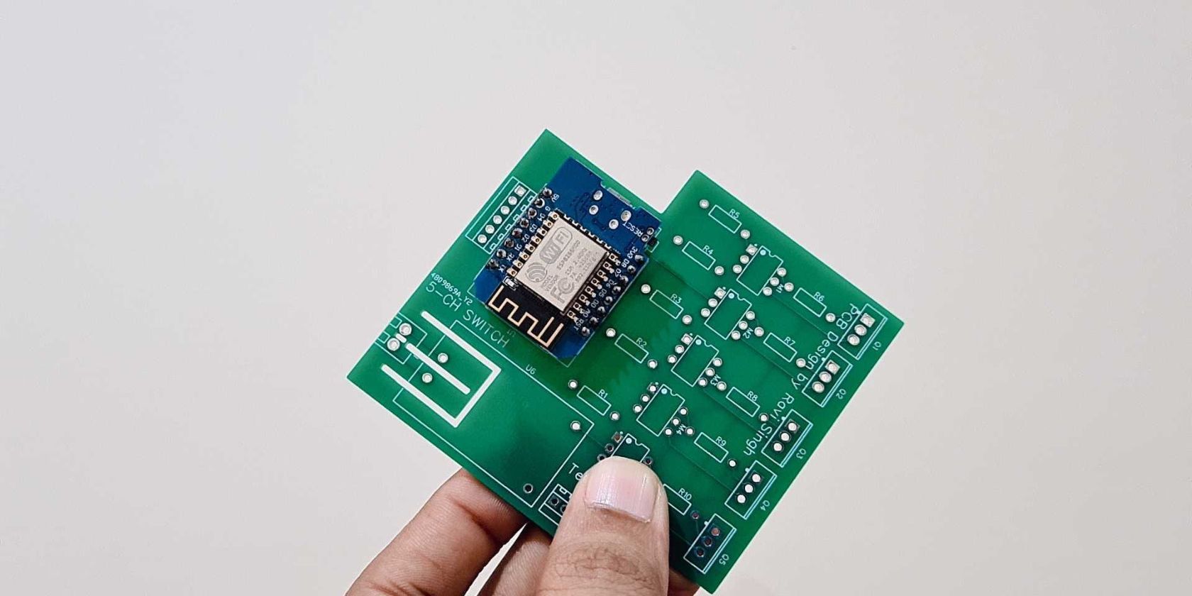
We have already designed the circuit board and done the hard part (new and improved). All you have to do is download the Gerber file, which you can use to have your PCBs printed or fabricated by any PCB manufacturer or supplier. FYI, we made 10 PCBs for $7 and paid $5 for shipping.
Solder the components on the board
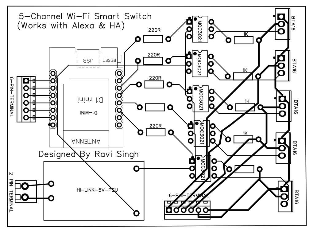
Assemble all components on the circuit board as shown on the circuit board. You can also use a generic PCB and follow the connection diagram below to manually assemble and solder all the components.
IMPORTANT INSTRUCTIONS
Do not mount and solder the D1 Mini directly on the circuit board. Follow these instructions to mount D1 Mini on the board.
- D1 Mini comes with male and female mountain stripes. Solder male mountain strip to D1 Mini.
- Solder the female mount strip on the board where we need to place the D1 Mini.
- Place the D1 Mini on the female headers soldered on the board to mount it on the board.
This will help you quickly disconnect or replace D1 Mini when things go bad.
If you don’t know or have never soldered before, we strongly recommend that you learn to solder before proceeding.
Flash the firmware
Once the components are mounted and soldered to the board, follow these steps to download, flash and configure the firmware on the D1 Mini to control the 5 solid state relay on the board.
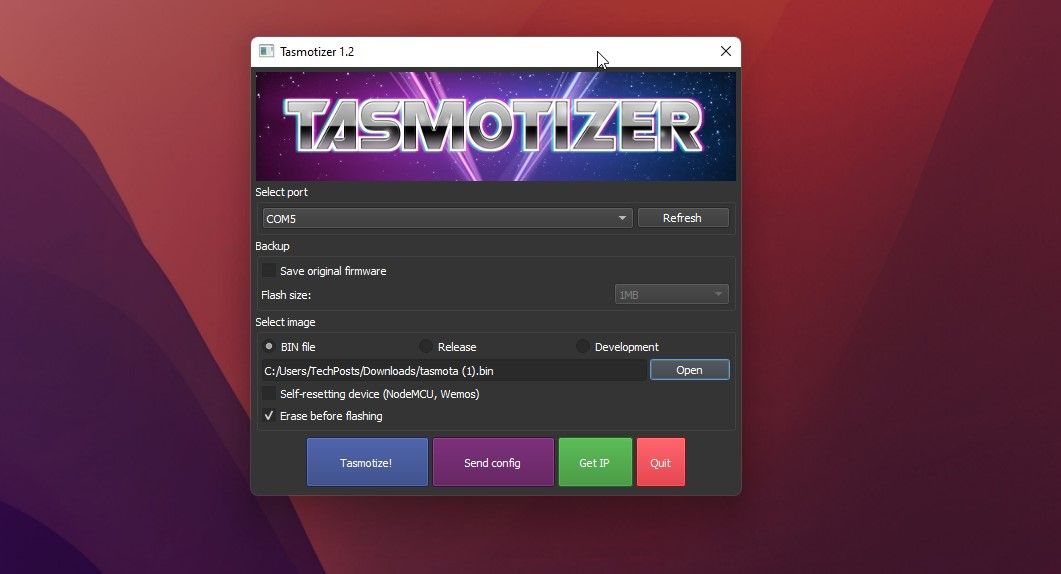
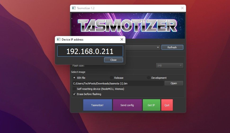
- Download the Tasmota firmware (file tasmota.bin) on your system and install the Tasmotizer tool (only available for Windows). You can also use the ESPHome flasher tool if you are using macOS or Linux.
- Start the Tasmotizer tool and connect the D1 Mini to your PC using the micro USB cable.
- press the Update Button.
- Choose COM Port to which the D1 Mini is connected.
- click Open and then browse the downloaded Tasmota firmware (.bin file).
- click Tasmotize. Wait for the process to complete. It takes less than a minute to finish.
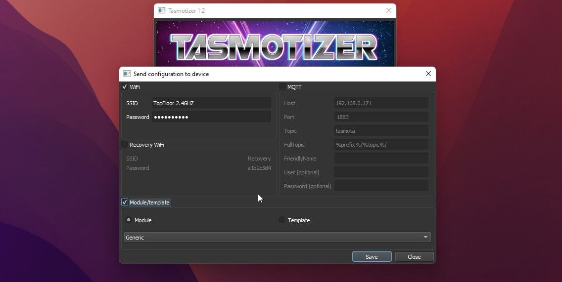
- Once the blinking stops, click send config Button.
- Choose Wireless Internet access and enter the SSID and password of your Wi-Fi network.
- click Module/Template and choose Generic.
- click Save on computer. You see a message’Configuration sent. The device will restart.’
- press the get IP button after a few seconds. This will show you the IP of the device when it successfully connects to your network.
- open that web browser and enter this IP. The Tasmota web interface opens.
If you want, you can also build a single-channel solid-state relay or an Alexa-supported single-channel smart switch yourself.
Configure the DIY Smart Switch
Once the Tasmota Web Interface (Web UI) opens, follow the steps below to configure the 5 switches for Wi-Fi and Alexa control.
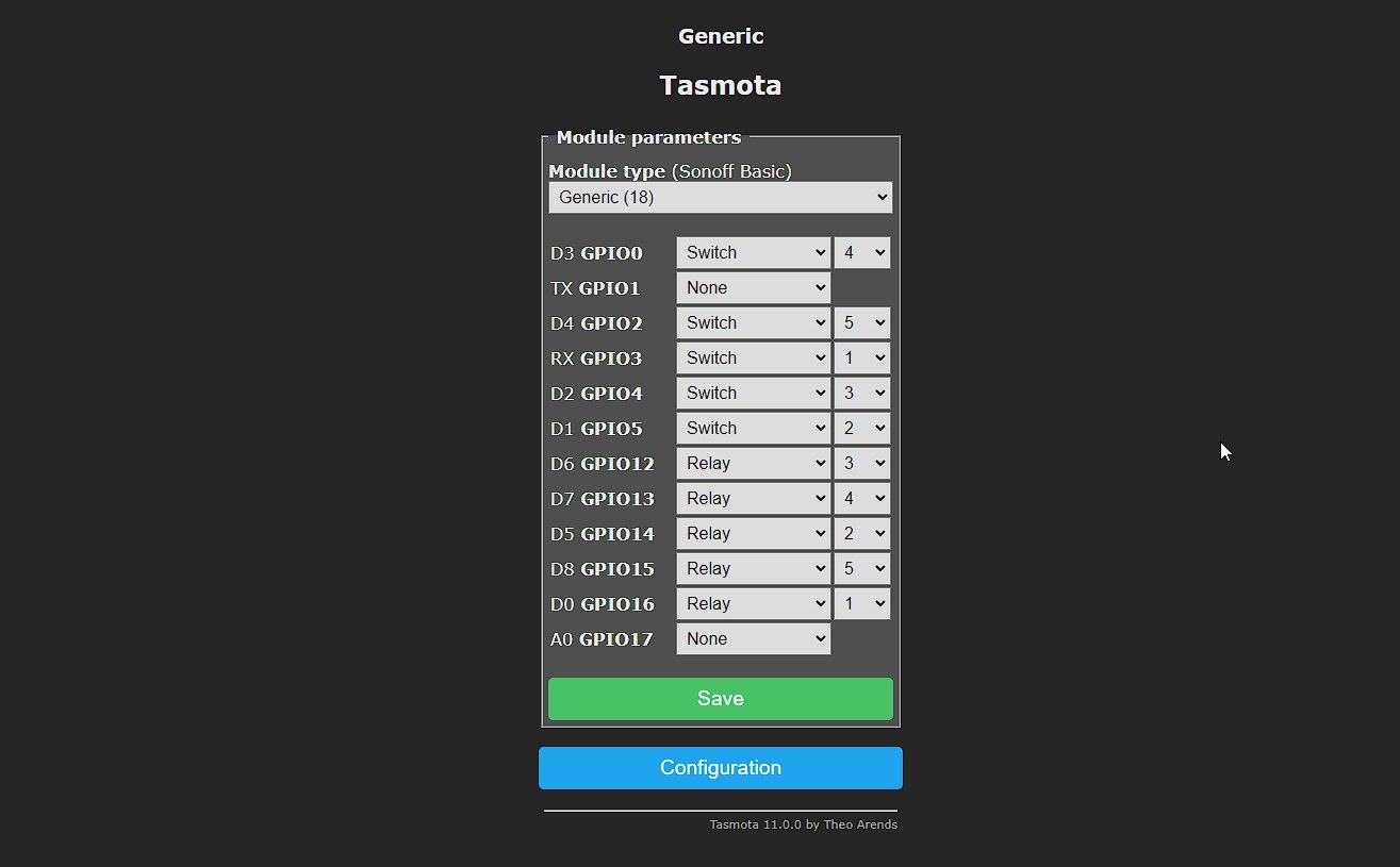
- click Construction > Configure module. Then refer to the following screenshot to choose the one relay and Switch Options followed by the channel number.
- Once you have selected all required channels for relay and Switch Options, click Save on computer. The device saves the configuration and restarts. The web UI will update automatically.
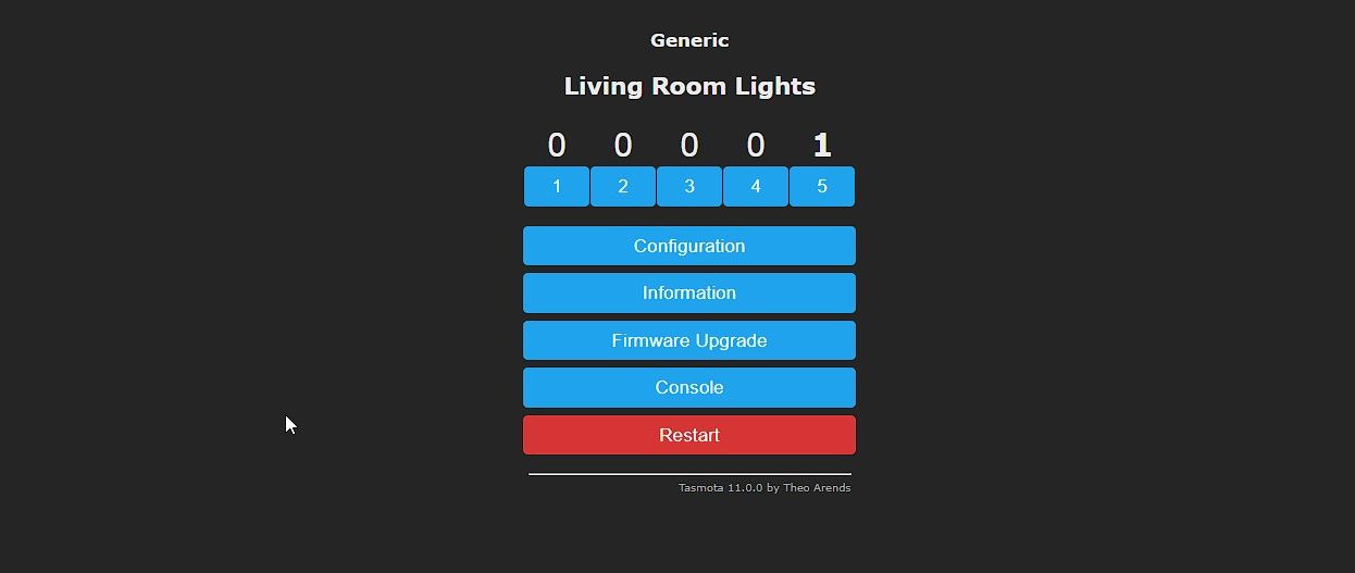
- You’ll see 5 controls on the Tasmota web interface. These can be used to trigger and control the solid state relays on the board to switch ON/OFF the connected load.
- 1 indicates that the switch is on while 0 shows OUT.
Enable Alexa support
To control this intelligent 5-channel smart switch with Alexa, follow the steps below:
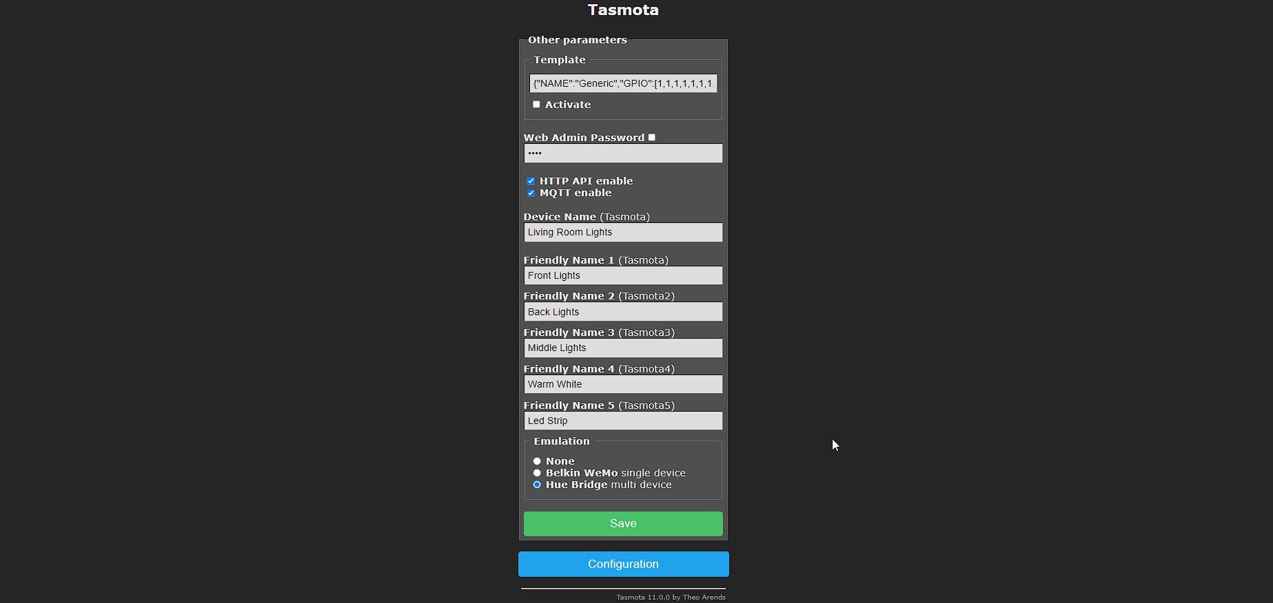
- In which Tasmota Web UIclick Construction > Configure others.
- In which device namegive your smart switch a nice name, e.g Smart switch in the living room. Also, enter the name of the 5 devices that you will control with this DIY smart switch. Since we’re using it for light controls, we’ve named them appropriately.
- Make sure you select Hue Bridge radio button and then click it Save on computer.
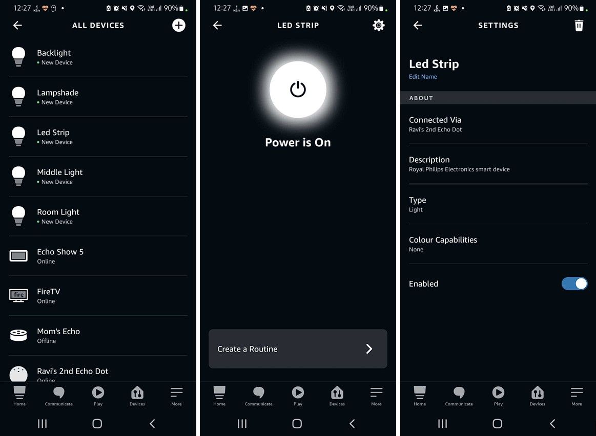
- The device will restart. You can now ask your Echo device to discover devices by typing “Alexa, find devices.’ You can also use the Alexa app > Devices to add these DIY Smart Switches.
- The devices will display the name you entered in the friendly name field in the Tasmota web UI. However, you can edit or change the names to your liking in the Alexa app. You will be recognized as Smart device from Royal Philips Electronics.
- Now you can control the Smart Switches with the Alexa app or with your Echo device. Just say, ‘Alexa, turn on the Led Strip.‘
Add to Home Assistant
To add this DIY smart switch to Home Assistant (HA), you need to enable MQTT on Home Assistant and then enter the MQTT details through Tasmota Web UI by following these steps:
- From the Tasmota interface, click Construction > Configure MQTT.
- Enter the Host IP (your HA IP), User, and password. Keep other things as default and click Save on computer.
- If auto-discovery is enabled on your HA (by default), you can see the 5 new Smart Switches in it settings > Devices & Services.
- You can select and add them to your HA dashboard and control the switches directly from the HA web UI with real-time switch status updates.
Provide silent DIY and private smart switches
You can build and use this 5-channel smart switch to control your fan, lights, or any home appliance that requires up to 200-300 watts of power. Because we built this switch with Solid State Relay (SSR), this switch operates silently with no clicking noise. Plus, you can control them locally even when there’s no internet, or if you’re connected to the internet, from anywhere in the world with the Alexa app.
