How to Make an RFID Door Lock With a PN532 and D1 Mini
Most commercially available smart RFID locks are easy to bypass. Here’s how to build one with certainty you can trust.
RFID-based door access control is not new. There are several RFID-based systems on the market that you can install for secure access. However, you can unlock most RFID door lock systems with a paper clip because the trigger switch is inside the module that is installed outside the door.
Instead, let’s build a fully secure DIY RFID-based door access control system using an ESP8266 and a PN532 RFID/NFC module that integrates with your existing electronic lock. Once installed, you can unlock your door with a registered RFID card/tag or smartphone.
things you will need
To build a DIY RFID based secure door access control system you will need the following:
- A WeMos D1 Mini. You can also use a NodeMCU.
- A single channel relay module.
- Micro USB cable.
- DuPont or female to female jumper wires.
- Female mountain strip.
- PN532 RFID/NFC module. You can also use the MFRC522. Wiegand or RDM6300 RFID sensor. We use PN532 because it has a smaller footprint and offers a good scanning range.
- soldering iron and tin.
Flash the firmware on D1 Mini
We will use the ESP-RFID project on GitHub to create our DIY RFID door access control system. Follow these steps to download and flash the ESP RFID firmware on your D1 Mini or NodeMCU.
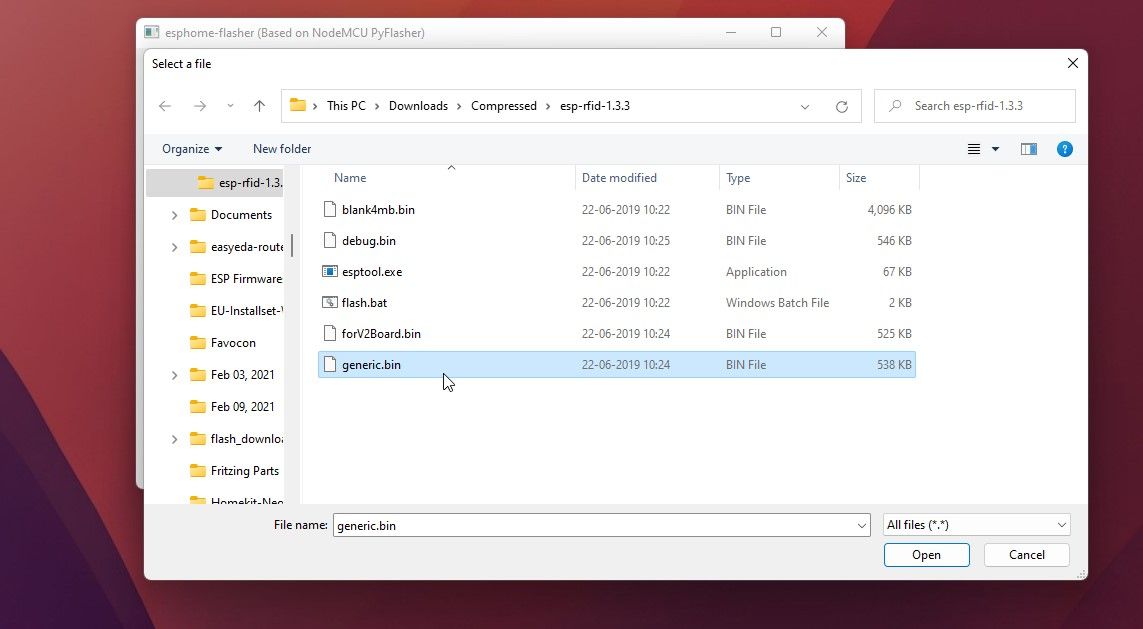
- Download the esp-rfid-1.0.2.zip file and extract the folder to your desktop. It contains some program files including a generic.bin firmware file. Optionally, you can also download the latest version v1.3.3 unstable structure.
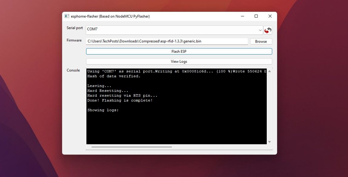
- Download and run the ESPHomeFlasher tool.
- Connect the D1 Mini or NodeMCU to your PC with a micro USB cable.
- In the ESPHome Flasher tool, click on the update icon and select the COM port your D1 Mini is connected to.
- press the search button and select the generic.bin File we extracted in step 1.
- click Flash ESP.
- This takes a few seconds. Configure the RFID settings
Configure the RFID settings
Once the firmware is flashed, reconnect the USB cable to D1 Mini and follow these steps to configure the RFID settings:
- Look in your smartphone’s Wi-Fi settings and connect ESP-RFID-xxxxx access point. It’s an open access point, so no password is required to connect.
- Once connected, turn off mobile data on your Android and iOS smartphones, then open the web browser.
- Visit the IP address 192.168.4.1and enter the password Administrator Log in.
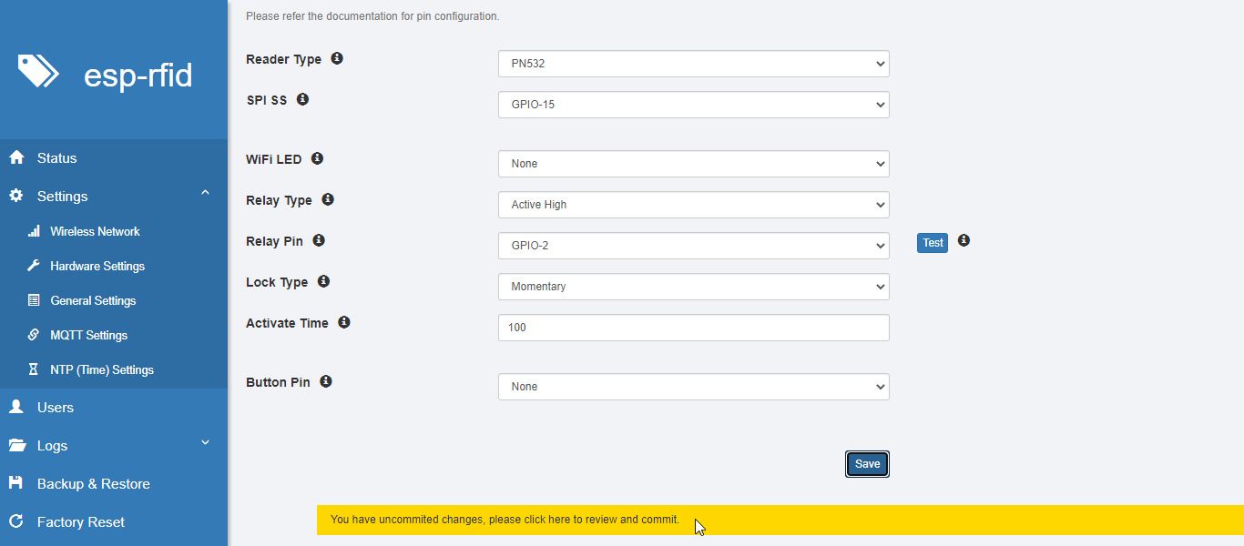
- click Menu > hardware settings and select the following options from the appropriate drop-down menus:
- Choose PN532 of the reader type.
- Choose GPIO-2 out SPI SS.
- Keep everything as default and click Save on computer
- Go to Menu > Settings > General Settings
- change that Administrator password from the default Administrator to something complex. This is a critical step and you must use a long and complex password to protect the devices from unauthorized access.
- You can edit those too hostname and choose if you want the device Automatic restart Every 24 hours, 7 days or 30 days.
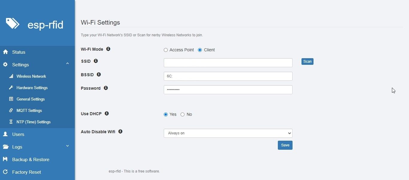
- Go to Menu > Wireless network and then enter a complex password to secure the access point. Again, use a strong password to prevent unauthorized access.
- You can also choose client option and connect the device to a wireless network.
- click Save on computer and then click the Text highlighted in yellow color at the bottom of the screen.
- click Save and restart.
- The device will restart.
Connect the RFID sensor to the D1 Mini
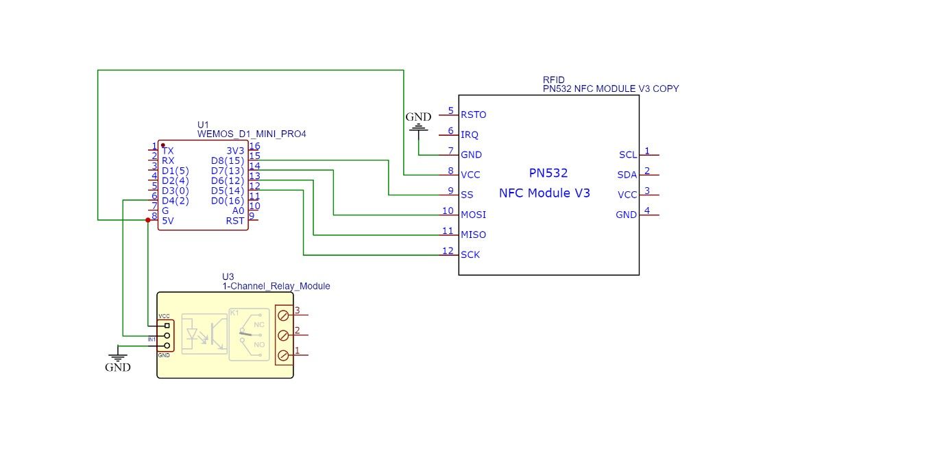
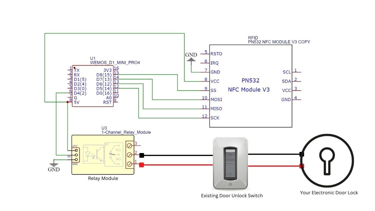
Disconnect the USB cable from D1 Mini or NodeMCU. Refer to the table and diagram below to connect the PN532 RFID/NFC sensor and relay module to the D1 Mini or NodeMCU board.
| NodeMcu/WeMos D1 mini pins | PN532 pins | relay module |
| D8 (GPIO-15) | ss | |
| D7 (GPIO-13) | MOSI | |
| D6 (GPIO-12) | MISO | |
| D5 (GPIO-14) | SCK | |
| D4 (GPIO-2) | ENTRANCE | |
| Vin/5V | VCC | VCC |
| G | Dimensions | floor |
Use the DuPont wires or Berg strips to connect or solder the D1 Mini or NodeMCU pins to the PN532 and the relay module. If you’ve never soldered a joint before, learn how to solder wires and electronics.
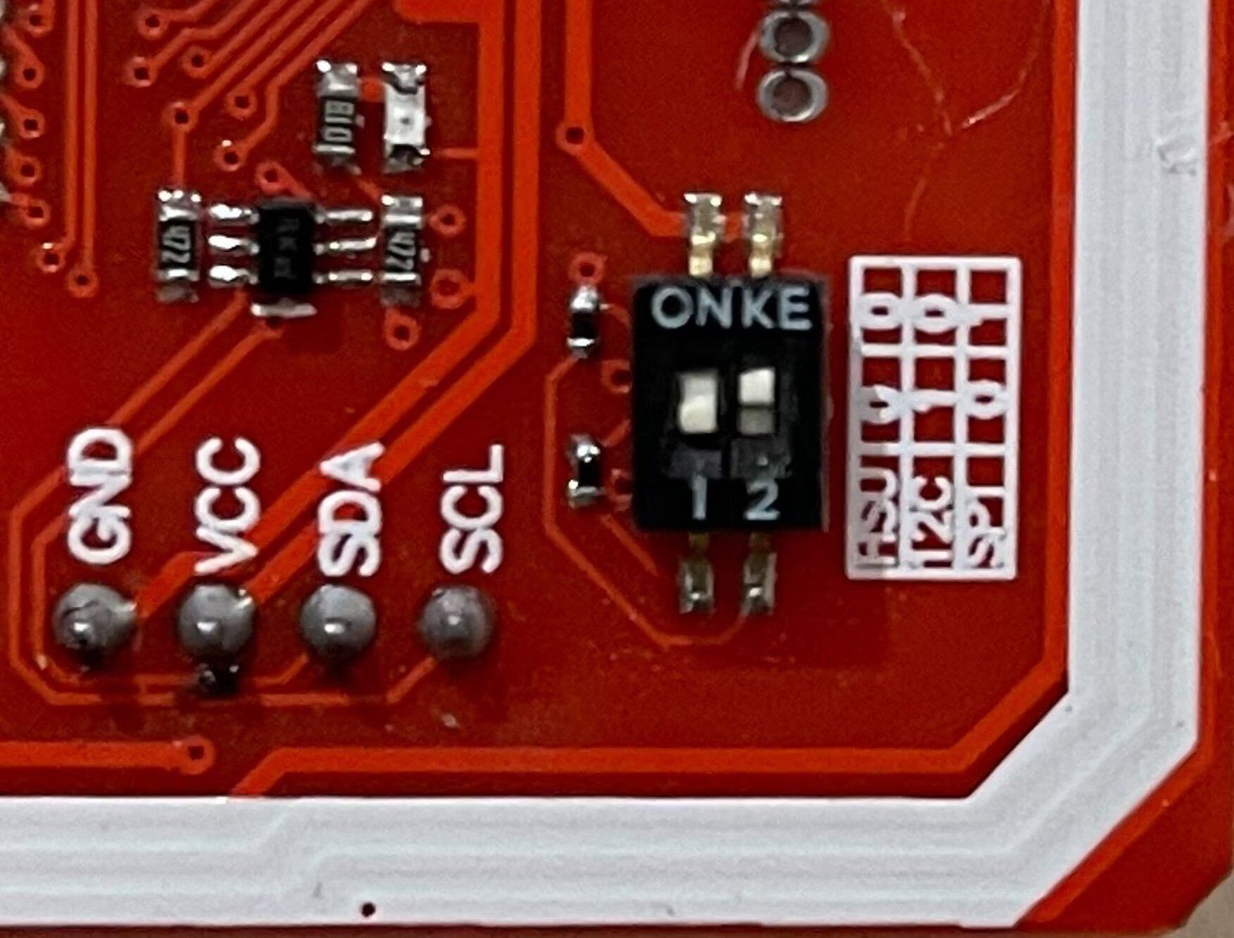
Ensure that the SPI protocol is enabled on the PN532 by setting the DIP switch to positions 0 and 1 as shown below.
Once the RFID module is connected to your NodeMCU or WeMos D1 Mini, you can start scanning the RFID card to register and add users to allow/deny access.
Add RFID cards/users
After connecting the PN532 module to the D1 Mini or NodeMCU, follow these steps to add and register users’ RFID cards or tags.
- Connect the USB power adapter to the Wemos D1 Mini or NodeMUC.
- Go to yours WLAN settings and connect to the esp rfid access point with the password you set up under wireless network the settings.
- Visit the 192.168.4.1 IP address.
- click Menu > user.
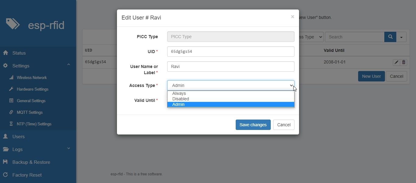
- Take an RFID card or tag and place it on or near the PN532 RFID/NFC Sensor. You will see a new one Add a new user Form with the scanned RFID tag ID.
- Enter the name of the person who owns the card or tag.
- Choose access type. you can choose between always, disabled, or Administrator. You should add a card for the admin (yourself).
- Choose Date of Expiry Date until when you want to allow or disable user access.
- click save Changes to save the user data.
Unlock the door via the web interface
After adding and storing users’ RFID cards, you can scan them with the PN532 sensor. Scanning cards with access type: Always or Administrator triggers the connected relay module. You can connect your electronic door lock power switch wires to this relay module to trigger the lock and unlock the door.
Here is a connection diagram you can refer to to connect the electronic door lock trigger switch wires.
Secure RFID door access control
Unlike other RFID door access control systems on the market that can be easily unlocked and have no user interface, this DIY RFID door lock system is Wi-Fi-enabled, intelligent, and offers an intuitive user interface to manage users and control their access at any time withdraw.
When you connect the DIY RFID module to your Wi-Fi network, you can access it on your network using the IP address assigned by your router. You can assign a static IP to this device and unlock the door by logging into the web interface and clicking Check button below the hardware settings. You can use a LAN cable or any 6 core cable to separate the PN532 and the D1 Mini or NodeMCU relay module to prevent unauthorized access and secure your door lock.
